IWEUA.COM
Lab Gruppen FP10000Q
Lab Gruppen FP10000Q

I have worked for many years with the VME team in Knutsford. Last time I popped in there were 4 Lab Gruppen
power amplifiers on the bench looking a little forlorn.
Two were an easy fix, some new audio pots in one, new 400V caps primary side of the switched mode in another
after a 3 phase fault wiped a pair out, surprisingly the bridge rectifier was fine.
That left two, a FP1000Q, a four channel unit which seemed fine visibly, the output stages seemed fine, but had no
audio output on any channel, the other an FP6400 took a while to repair, and only this evening am I happy it is fully
functional.
Fixing the FP1000Q : March 2020
The FP1000Q has a relatively straightforward, accessible design, but I did spend hours absorbing the service
manual that I have marked up and provided here.
The block diagram is the only place some of the most important control chips are listed, for example, U414 the chip
controlling the channel MUTEs, the actual cause of the mute output.
The short story is that the Atmega16L chip had failed, shorted internally 5V to 0V ( check 5V at test point Pin 2 ISP
header port ) This was an odd and unexpected fault as normally control circuitry is well protected by at least two
levels of power regulation, primary PSU and further linear regulation to 5 / 3.3 V as in this amplifier.
A quick clue ( for any uP ) being the crystal was not running which I find is one of the easiest things to check. I took
the crystal out and it worked fine on a spare Arduino board I had ( 3.28MHz )
It seems a little odd to loose a uP at all, stranger that it should cause the failure of all audio, read on.
I will start the conclusion first.
All components refer to Channel 1, eg R29, thus channel 2 equivalent is R129 / Chan 3 = R329 etc
With reference to Page 21 of the PDF.
If the uP is NOT running, pin 15 of U414 is LOW, and thus Pins 11-14 signals MUTE channels A/B/C/D are not
enabled and thus 'high Z'.
Page 22/3/4/5 : MUTE A/B/C/D lines float up to 2.4V via R29 ( for channel 1 ), enough pull up for Q23 and Q4 to
turn ON.
Q23 Collector pulls opMute LOW, which under normal conditions would hold at around 15 Volt via R62 and Zener
D17 (15V ) detailed on Page 1
Further, Q4 pulls pin 2 of U3 low, the opto isolator limiter ,thus limits the amplifier output significantly even if Q23 is
removed ( Channels 1 & 2 were both faulty ).
This was a strange fault. I had tested each of the amplifier boards powered from a +/-32V power supply. The MUTE
signal is pulled high to ~14 V from the 160V +VRail, dropped through R62 and regulated by D17 15V Zener.
The relevant parts of the MUTE signal ( which changes name from MuteA to Mute to OpMute ) over three pages


Replacing the Atmega :
Removing the chip was straightforward. Before placing the new one, I checked that the power rails were working
with no chip present, they were and were good once the new chip was installed.
The ATMega16L ( L for low power / low voltage , you will note that the chip does not receive 5V from Q404, the
emitter follower providing about 3.5V to pins 5/17/38)
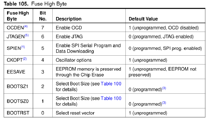
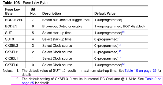
I used avrdude with a Sparkfun Pocket AVR Programmer to read Low Byte, High Byte and Lock byte of the chip.
The Atmega 16L data sheet Fuse settings with the CKSEL settings found on Page 25
Removing the chip was straightforward. Before placing the new one, I checked that the power rails were working
with no chip present, they were and were good once the new chip was installed.
The ATMega16L ( L for low power / low voltage , you will note that the chip does not receive 5V from Q404, the
emitter follower providing about 3.5V to pins 5/17/38)
I used avrdude with a Sparkfun Pocket AVR Programmer to read Low Byte, High Byte and Lock byte of the chip.
The Atmega 16L data sheet Fuse settings with the CKSEL settings found on Page 25
Conclusion
I did and didn't fully fix the board.
I was quoted a price from AmpMan who provide an excellent service, to replace the entire board, the Atmega not
available as a spare part.
I DID fix the FP6400 fully :
More on that here which was more of a traditional, large amplifier repair.
I can always be emailed with the hex file for this chip at w e b 2 0 a t i w e u a d 0 t com
From factory the Low Byte is 0xE1, the chip running from internal oscillator.
From the manual it looks like the Low Byte low nibble ( bits 0-3 ) needs to be set to 1111 for 3.28 MHz ext crystal.
Reading the Low, High and Lock bits from another FP1000Q
LOW : 0xBD
HIGH : 0xD0
LOCK : 0x3C ( LB1 & LB 2 set to Zero so you can't copy a good chips....shame... )
To read fuses
AVRDUDE + a USBtiny or USBASP, the Sparfun Pocket AVR Programmer is my current choice for support and
avrdude -c usbtiny -p m16 -P usb -U flash:r:-:i
The terminal mode is a straightforward method of writing to fuses directly
avrdude -c usbtiny -p m16 -P usb -u -t
>>dump lfuse // you can just type 'd lfuse'
then to write to the fuse
>>write lfuse 0 0xEF // this will set all bits of CKSEL to 1 ensuring the external Crystal will work
>> d lfuse
>> quit
So that is as far as I got. I removed R29/R129/R229 and R329
And I shorted across the LED diode ( Pins 1&2 ) of the limiter opto U3/U13/U23/U33 to prevent limiting.
This brought the amplifier fully up, but far from factory restored as the control side was not working, which for this
application had never been used anyway, so no great loss.
See a further page on the fixing a FP6400Q